
Home / Free Tools And Solutions / WiFi Garage Door Opener, With Real HTTPS and a Proper App
WiFi Garage Door Opener, With Real HTTPS and a Proper App
Introduction
Nearly any old garage door opener can become a smart opener, controllable over local WiFi, the internet, or Bluetooth. The cost is around $40 CAD ($30 USD) in parts at the time of writing. The opener can then be operated from a simple web UI, a phone app (Android device only), or both.
Some benefits over buying a smart opener:
- No need to physically replace the garage door opener
- Cheaper than replacement, especially in exceptional cases (for example, a 9-foot door that needs an extension kit)
- Reduced dependence on manufacturer remotes, which can be pricey
- No accounts or subscriptions
- Not dependent on manufacturer apps, which can be
Chamberlain shut off third-party access to the myQ API in 2023 and broke Home Assistant and Homebridge setups that had been in daily use. The Verge →
Nexx disabled internet control of its garage controllers for every customer after a security flaw, leaving only short-range Bluetooth. PCMag →
Genie changed the Aladdin Connect API in 2024 and unofficial Home Assistant and Hubitat integrations stopped working. Hubitat Community →
Ryobi discontinued its opener line after a patent case and left owners on an app that stopped getting real support. SlashGear →
- Bluetooth control as a fallback where internet access is unreliable
- Full control for expansion and customization
This writeup includes a hardware list, wiring instructions, networking steps, firmware instructions and code, the app source, and a downloadable APK for Android.
Who should NOT attempt this project
This project is intended for people with a solid understanding of electronics, networking, and basic automation. You should be comfortable with low-voltage wiring and with choosing appropriate wire for small DC loads. Familiarity with coding, compiling, and flashing is recommended. You will also need basic networking knowledge: connecting a device to a 2.4 GHz WiFi network, assigning a static IP, and troubleshooting connectivity from the router. It is equally important to understand how your specific garage door opener works so you do not bypass or disable built-in safety features such as IR sensors or auto-reverse. You should be confident using hand tools to mount components securely. If any of this is outside your comfort zone, especially electrical safety or garage door mechanics, this project may not be a good fit.
This guide is not a step-by-step blueprint for every opener. It documents one working build with specific parts and methods. The ideas and wiring approach are broadly applicable, but individual setups differ in important ways. Readers are expected to understand the principles and adapt them. This is not a connect-the-dots tutorial. It is a practical reference for people with the background and initiative to fit the solution to their own hardware.
Project history
The project started on July 17, 2025, on an ESP8266 with magnetic reed switches and a plain HTTP interface. The reason to replace the ESP8266 was reliability after power loss: it failed regularly after thunderstorms and needed a reflash.
The ESP32 recovered cleanly from the same kind of power interruption. The ESP32 also has Bluetooth built in, which led naturally to using it as a fallback when the network is down. Getting Bluetooth working required a proper Android app rather than relying on the built-in web interface.
HTTPS was the piece still missing: secure access from anywhere without extra infrastructure. Getting that reliable enough on a plain ESP32 is what motivated the later move to the ESP32-S3.
Separately, the reed switches themselves had a problem: their detection range was too tight for a door that does not stop in exactly the same position every time. That was solved by switching to long-lever microswitches.
The current setup uses microswitches that read correctly every time, and an app that reaches the door over local HTTPS, internet HTTPS, or Bluetooth, in that order of preference.
Requirements
Skills needed (or willingness to learn them)
- Low-voltage wiring and choosing appropriate wire for small DC loads.
- Enough understanding of the specific garage door opener to avoid bypassing or interfering with its safety features while locating and testing the wiring.
- Confidence with hand tools for mounting components securely.
- Coding, compiling, and flashing firmware, specifically ESPHome.*
- Basic networking: 2.4 GHz WiFi, assigning a static IP, basic router troubleshooting.*
- Ability to use code held in a GitHub repository.*
- Using Android Studio, if rebuilding or customizing the phone app.*
- Generating a self-signed HTTPS certificate and creating a Bluetooth shared secret.*
*This page is written so a capable AI model, pointed at it, can help with the starred items above.
Hardware needed
- Garage door opener with accessible wall-control terminals. Most openers with a wall button or remote qualify; some newer models with enhanced security features will not.
- 2.4 GHz WiFi network access.
- ESP32-S3 with PSRAM (an N16R8 or equivalent).
- 5V relay module.
- Long-lever microswitches (two), plus flexible striker (spring material) to push on the lever.
- Various hand tools and fasteners for mounting the switches and the board (drill, screwdriver, screws, JB Weld, and the like).
- Basic wiring and soldering tools, and a multimeter.
- A computer with a USB port for flashing. A Linux desktop was used in this example and is recommended.
Optional requirements
- For access over the internet instead of only local WiFi, a way to forward web traffic to a particular IP. This example uses
DuckDNS is a free dynamic DNS service. A small client on the router or the LAN keeps a chosen hostname (for example, yourname.duckdns.org) pointed at the home's current public IP, so the address keeps working after the ISP changes it. DuckDNS →
with the router's port forwarding. - To build the app in Android Studio, a 64-bit computer with at least 8 GB of RAM (16 GB if you use the emulator) and a CPU from roughly 2018 or later, such as an Intel 8th-gen Core i5, an AMD Ryzen, or Apple Silicon. Several gigabytes of free disk space are also required. A prebuilt APK is provided if you do not want to compile the app.
- Connecting over Bluetooth requires an Android phone to run the app.
Getting started
The project starts at the existing wall switch. For this example, it is a 2004 Wayne Dalton Quantum opener. This opener operates at an odd frequency, which makes replacement remotes and keypads expensive and hard to find, so being able to use a smartphone as a remote is a real benefit. The existing switch is battery powered, and the batteries needed frequent replacement, so before this project a 12V LED power supply was hardwired in to eliminate the batteries.
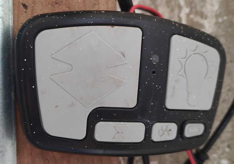
The first step is locating the button that tells the opener to open or close the door. In this example it is the large button on the left with the up/down arrows. That button is the target of the project.
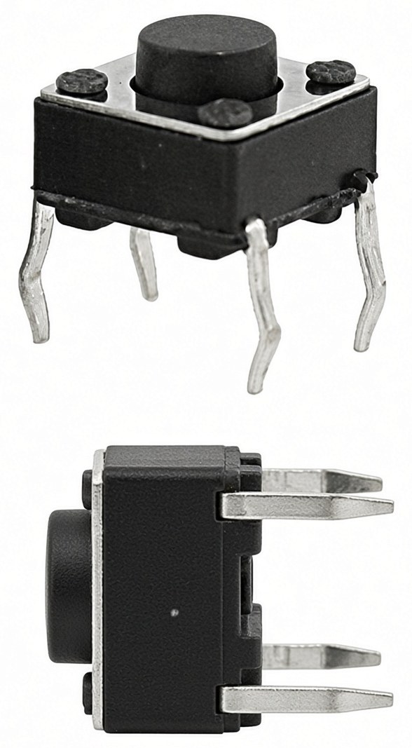
Beneath the target button is a 4-pin momentary switch. When pressed, it briefly connects one pair of pins to the other and completes the circuit.
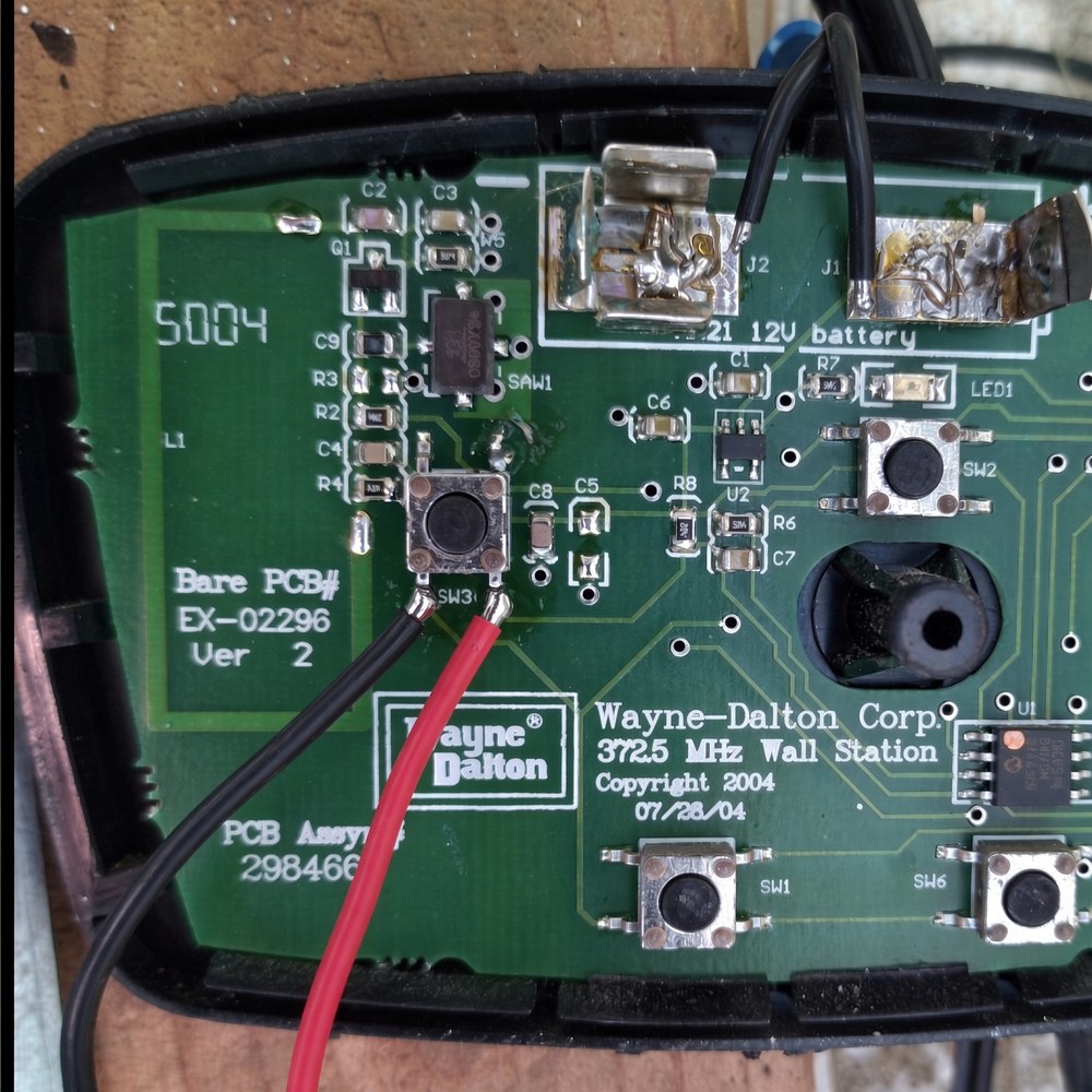
If you can locate a switch like this and solder wires to it, you will likely be able to complete this project.
Using a multimeter, it was determined that:
- The left-side pins are connected to each other and to ground
- The right-side pins are connected to each other and sit at 5V
- Pressing the button bridges the left and right sides, closing the circuit
To simulate that press electronically, a relay connects the left and right sides together for a moment. The black and red wires shown in figure 3 above go to the relay and carry this simulated press.
Hardware descriptions
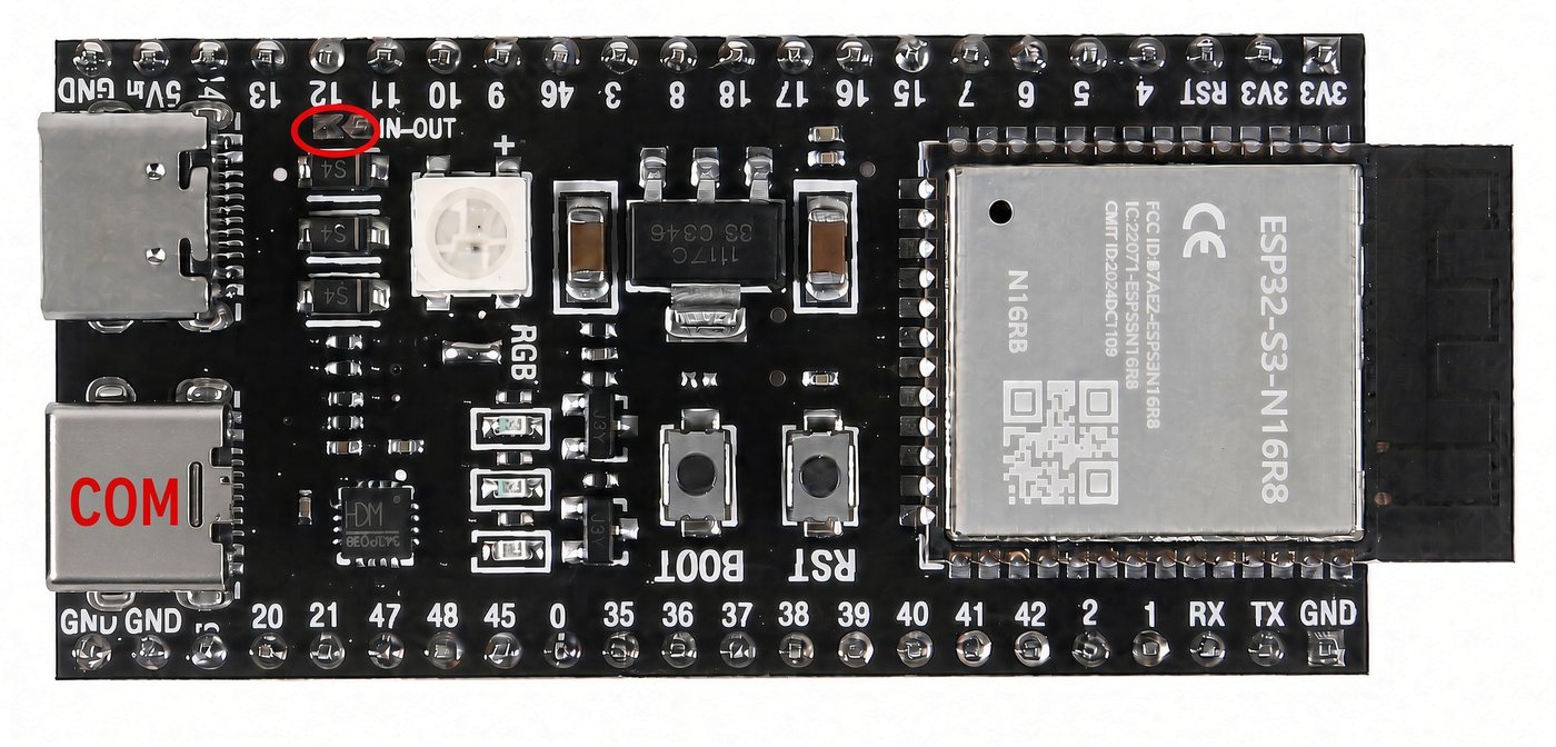
ESP32-S3
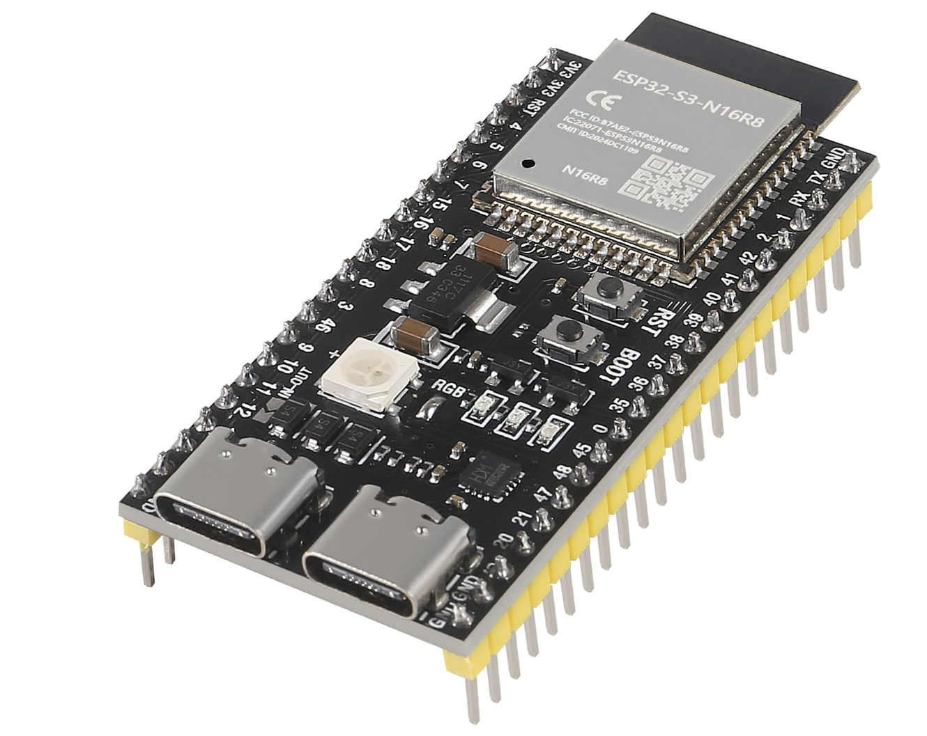
The ESP32-S3 is a small, WiFi- and Bluetooth-enabled microcontroller that serves as the brain of this project. It was chosen because it is cheap (about $13 CAD), easy to work with on Linux, and readily available on Amazon with fast, free shipping.
To use it, connect it to a computer over USB, flash it with firmware, and configure it to join the WiFi network and control the relay. Once set up, it can respond to commands from a web interface.
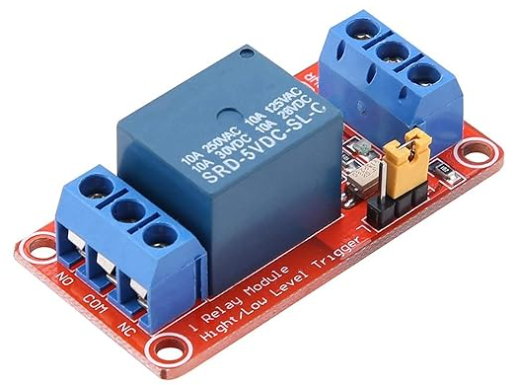
1-channel 5V relay module
This project uses a 5V 1-channel relay module with optocoupler isolation. It can be powered directly from the ESP32-S3, so no extra power supply is required.
The optocoupler adds a layer of protection between the relay and the ESP32-S3. The relay lets the chip simulate a button press by briefly closing the circuit, the same as pressing the wall switch by hand.
Mechanical lever switches
Mechanical lever switches are simple contact sensors used to detect whether the garage door is open or closed. When the door presses the lever, the internal contacts close (or open, depending on the wiring).
These switches have NO (Normally Open) and NC (Normally Closed) terminals. For this project, the switch is wired so that it only reports the door as closed when the circuit is complete, so the system does not falsely report a closed door.

Setting up the hardware and firmware
To program the ESP32-S3, the YAML file is compiled into firmware and flashed onto the chip over USB using ESPHome. This process translates the YAML into low-level C++ code that directly controls the chip's pins and functions. Once flashed, the ESP32-S3 connects to the WiFi network and begins running the firmware.
The chip talks to connected parts through its GPIO (General Purpose Input/Output) pins, labeled on the board as GPIO21, GPIO41, GPIO42, and so on. The YAML uses those same numbers (for example, GPIO21 for the relay). The WiFi name and password, a static IP such as 192.168.0.250, and the WebUI login are stored in secrets.yaml so the device is easy to find on the network and the main YAML can be shared. HTTPS will not work until a certificate is generated and compiled into the firmware. The Bluetooth shared secret is a separate string that must match on the device and in the app. Specific steps are in the repository README.
To flash the firmware, use the ESPHome command-line tool. This runs on Linux, Windows, and Mac. The tool compiles the YAML and sends the firmware to the ESP32-S3 over USB. After the first successful flash, later updates can be sent over the network (OTA).
When flashing the chip, use the port labelled UART/COM. The ports are labelled on the back of the chip. Some versions of the board need the IN-OUT (see Figure 4) soldered closed to allow 5V from USB to reach the 5V pin.
A web interface is built into the firmware. Once the chip is online, visit it from any browser on the network at the static IP (for example, https://192.168.0.250) to see door status, toggle the relay, or confirm that everything is working. Use https, not http. A username and password are required. The browser will ask for them before the page loads.
This example uses that built-in WebUI. It displays the switches and allows relay control from the YAML.
The YAML and the rest of this build are on GitHub: https://github.com/jasoncousineausolutions/garage_door_https
garage_door.yaml matches the wiring in this guide. Change fields as needed for a different setup.
Copy secrets.example.yaml to secrets.yaml and put the WiFi name and password, static IP, and WebUI username and password there. Those values do not go in the main YAML. The username and password are not optional.
Switch installation
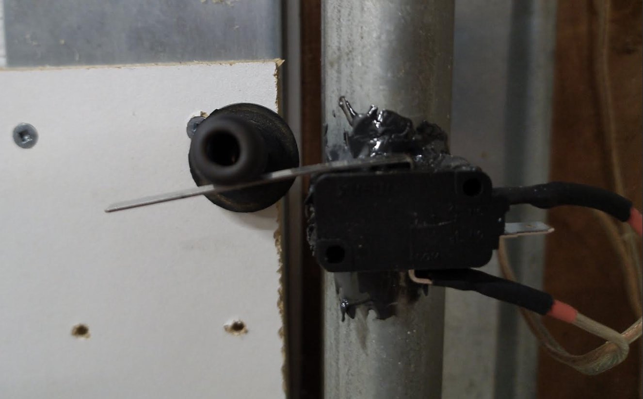
With the ESP32-S3 flashed and connected to WiFi, wiring can begin. The mechanical lever switches are a low-risk place to start. One switch should click closed when the garage door is fully closed, and the other when the door is fully open.
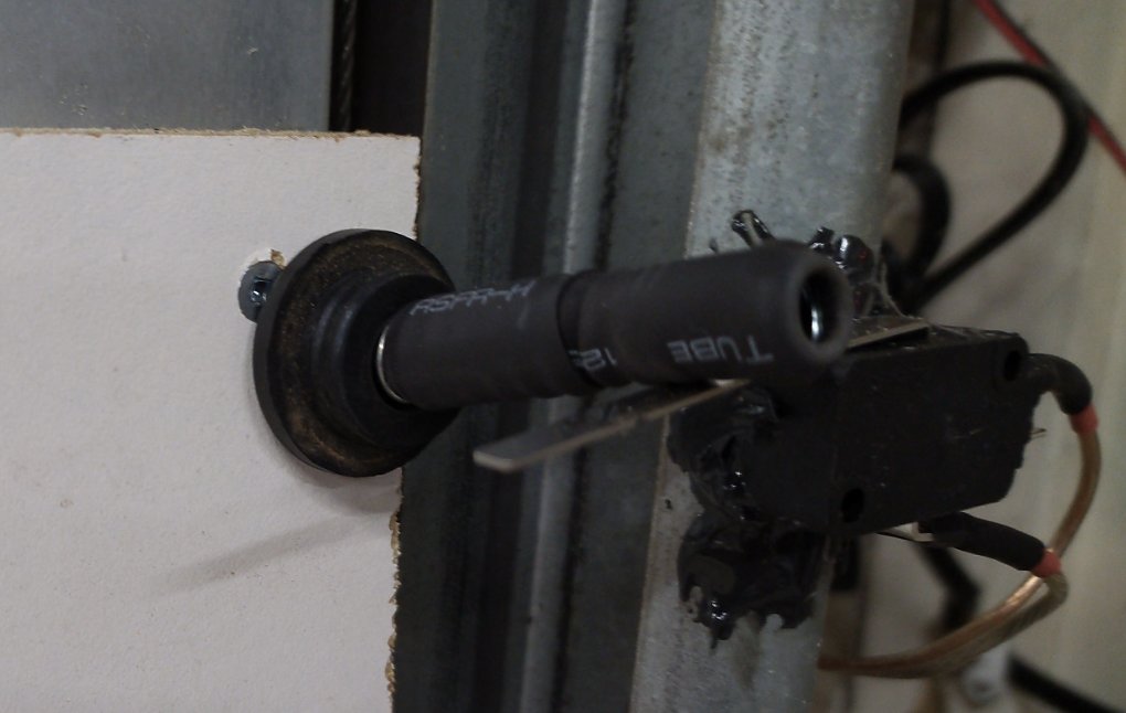
Fast-setting JB Weld epoxy works well for attaching the switch to the track. Scrap lumber was used to mount a flexible striker that presses on the lever (in this case, a spring with shrink-wrap on it).
A note about the flexible striker and the lever switches
The example garage door rarely stopped in the same place twice: on open, it would overshoot its final resting position by nearly an inch and bounce back. A flexible striker absorbs that variability. For some garage doors, the lever's own flex may be enough, so add a striker only if needed. Examples of flexible strikers are shown below.


Wiring
Speaker wire was used on the COM and NO (Normally Open) terminals. It is inexpensive, sold in many lengths, and has two conductors joined together, so one tidy run covers both connections. Speaker wire also usually has polarity markings, such as red and black, or copper versus silver conductors. Those markings matter on a long run, when it is hard to tell which conductor is which.
Fully closed switch
NO → GPIO41COM → GND
Fully open switch
NO → GPIO42COM → GND
After the switches are wired, this is a good time to confirm that the ESP32-S3 is online and reporting switch status. The status should update almost immediately. If you are using the provided YAML, the WebUI username and password come from secrets.yaml.
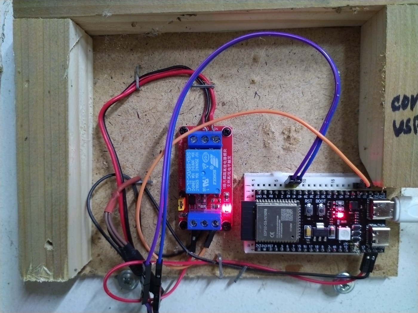
Next, wire the relay to the ESP32-S3.
Relay IN → GPIO21Relay DC+ → 5VRelay DC- → GND
After that, the relay should click from the WebUI. It looks something like this:
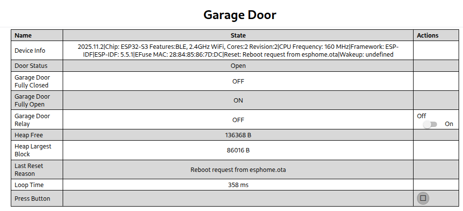
With the relay clicking on demand and the switches reading correctly, wire the relay to the garage door controller. In this example there was room inside the controller, so the relay wires were soldered to the pins on the left and right of the momentary switch. The plastic housing around the switch was modified so the wires could pass through.
COM on the relay is soldered to the left side of the switch, which was ground. NO on the relay is soldered to the right side, which is 5V.
The YAML sets how long a simulated press lasts. In the example YAML, the relay stays on for half a second.
Operating the door
With the relay wired to the wall-switch circuit, the door can be controlled and its status watched from the WebUI.
At first the WebUI is only available on the local network, at the device's static IP over https.
To reach it from outside the local network, this example forwards a router port to that IP and uses DuckDNS so the public hostname stays current when the home IP changes. A VPN onto the local network works as well. In either case the address is https, not http, and the WebUI username and password are required.
Making HTTPS Work on an ESP32
ESPHome has no built-in TLS support. This is a long-documented gap: ESPHome's own feature-request tracker has carried an open request for SSL/TLS support since 2019, and a separate, more detailed request from 2023 explains specifically why it's hard: no public domain name for a real CA certificate, browser mixed-content policies, and more. Common advice is that HTTPS on an ESP32 isn't practical without an always-on companion device, such as a Raspberry Pi, in front of it.
What actually breaks. A plain ESP32 without external memory can serve HTTPS at first. Each TLS handshake allocates 30 to 40 KB of RAM, and without PSRAM to hold that, internal RAM fragments permanently, connection by connection.
| Plain ESP32 | ESP32-S3 (N16R8, with PSRAM) | |
|---|---|---|
| Free heap, idle | 98,540 B | 156,316 B |
| Largest free block, idle | 81,920 B | 106,496 B |
| Largest block after HTTPS use | falls to 8,192 B | holds at 86,016 to 90,112 B over 15- and 56-hour runs |
On a plain ESP32, the largest available block falls from about 72 KB to 38 KB to 8 KB within a handful of HTTPS connections, after which nothing can connect.
The fix. ESPHome's web_server_idf component, forked to use Espressif's esp_https_server instead of the plain-HTTP version, plus two configuration changes that make it hold up over time instead of just working in a demo. CONFIG_MBEDTLS_EXTERNAL_MEM_ALLOC routes TLS allocations to PSRAM instead of internal RAM. lru_purge_enable evicts the least-recently-used session once connection slots fill, instead of letting a stale session block new ones with cryptic TCP resets. There are 7 session slots total, 3 reserved, 4 usable, and one leaked session during testing was held for about 20 hours, the kind of case this setting exists to catch.
Hardware and cost. Requires an ESP32-S3 with PSRAM, about $13 CAD each. The commonly recommended alternative, adding a Raspberry Pi in front of a plain ESP32, costs more and adds a second device to run: the cheapest Pi that would have worked ran over $50 CAD plus cable, power supply, and shipping. The ESP32-S3 approach needs none of that.
GPIO notes. Avoid GPIO39 and 40 for relay outputs; they're JTAG pins that pull high at boot and can trigger unintended actions. GPIO35 to 37 aren't available on boards that use them for the PSRAM interface.
Security. A self-signed certificate is compiled into the firmware with a 10-year validity period. This hasn't had a formal security review. The Android app adds certificate pinning on top of that, covered below.
Measured, not estimated: loop time normally runs 18 to 30 ms, rising to 300 to 390 ms during a TLS handshake, the likely source of the roughly 350 ms delay on a press (end-to-end press latency itself wasn't directly measured). Over about 56 hours with the HTTPS port exposed to the internet, 73 failed handshake attempts were logged, consistent with routine automated scanning rather than anything targeted, all rejected without incident.
The full configuration is in garage_door.yaml, directly from the repo. Three sections carry the story:
external_components:
  - source:
      type: local
      path: components
    components: [web_server_idf]
esp32:
  board: esp32-s3-devkitc-1
  framework:
    type: esp-idf
    sdkconfig_options:
      CONFIG_MBEDTLS_EXTERNAL_MEM_ALLOC: "y"
psram:
  mode: octal
  speed: 80MHz
The Android App
The final piece of the project is the Android app. While the app was originally created as a way to make the Bluetooth connection work reliably, it has since evolved over three dozen iterations to become a major integrated component, and is key to having a tool that can compete with commercial Smart openers. The app not only provides a simple and clean user interface and a method of sharing (and revoking) door access, but it also contains within its code the lessons of several weeks of real-world testing.
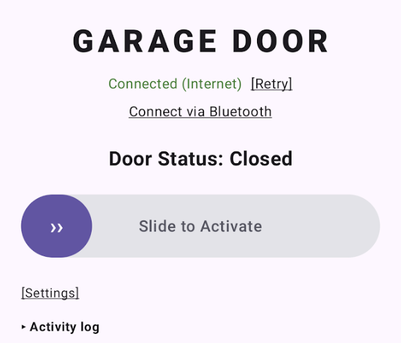
The source code for the app is provided for whoever wishes to view or customize it. The code is the place to see all the conditions that were found to be necessary to keep the door secure, the opener working reliably, and the status reporting accurately during many rounds of testing based on different connection methods, multiple client devices, unreliable internet connections, etc. Some of the choices are specifically described below.
A note about connection methods
Three ways exist to reach the door.
-
Local HTTPS is the simple path. Once the ESP32-S3 has a static IP, a browser on the same WiFi can open
https://followed by that address. The self-signed certificate means a security warning to click through, then a username and password. Some browsers forget those credentials and ask again. The built-in WebUI works. It is not a good daily remote.The advantage is reliability. If the home WiFi is up, this path works with no internet. Range is usually better than Bluetooth, depending on where the access point sits. With only this path, a phone can replace an ordinary garage-door remote.
-
Internet access is what makes it behave like a smart opener: status and control from anywhere with a connection. The WebUI drawbacks remain (certificate warning, awkward page, typing the password). Two usual ways to offer internet access are a VPN and port forwarding. With internet access, a phone can replace a smart opener.
A VPN, for this project, means the phone can reach the ESP32's LAN IP as if it were on the local network. The chip itself does not run the VPN.
Port forwarding sends traffic aimed at the house to the ESP32. Almost every router can handle port forwarding. This example uses DuckDNS so the public hostname stays current when the ISP changes the home IP. Some routers have no hairpin NAT: port forwards apply only to traffic that arrives on the WAN interface, so a phone on the LAN that uses the public hostname never reaches the ESP32. Where hairpin NAT exists, it still fails if loopback is disabled, the forward is bound only to WAN, or the router's DNS-rebind protection will not resolve that hostname to a LAN address. Without an app, the user has to pick between the LAN address and the public hostname, and at the edge of WiFi they may not know which network they are on.
-
Bluetooth needs no network. Range is short, and connecting by hand is fiddly. An Android app was the only method that stayed reliable. Door status over Bluetooth was attempted and dropped. A usable reading may be possible, but someone in Bluetooth range can see the door, and finishing that path was not worth the time.
What makes the raw WebUI clumsy:
- Choosing the LAN address or the public hostname, including while walking in or out of WiFi
- Hairpin NAT, or setting up a VPN
- Clicking through the self-signed certificate warning
- Entering credentials more than once
- The built-in WebUI itself
- Bluetooth by any method other than the Android app
The app source, and a precompiled APK, are on GitHub.
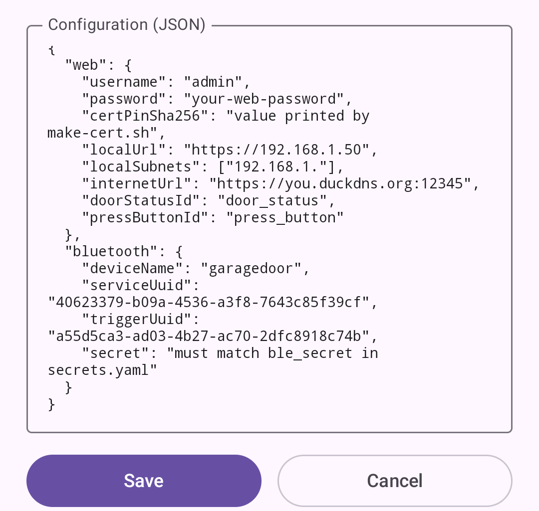
A sample config file is needed on first open of the app.
The important design choices:
- The app is one place for local HTTPS, internet HTTPS, and Bluetooth. Most of the connection complexity (see “A note about connection methods” above) is hidden. Operating the door can be a single control.
- The app chooses its own path, without asking. It compares the phone's IP address to the configured local subnets to tell whether it's on the same network as the device: on that network it tries the local address first and falls back to the public hostname, and off it the order reverses. Whichever address answers first is kept until a request fails or Retry is tapped.
- Bluetooth is manual. “Connect via Bluetooth” is a fallback for when the network is down. The app checks whether the ESP32 is in range and tries to connect. Door status is not shown over Bluetooth. (Status over BLE was tried and abandoned; at that range the door is in sight.) “Retry”, or walking out of Bluetooth range, sends the app back to the web addresses.
- Presses are dropped early and never queued. A press is sent only if the connection was recently checked and found to be intact. If nothing happens, press again after a second. Nothing stacks. On the device, web, app, and Bluetooth all go through one script that will not fire more than once per second, so multiple clients cannot stack presses.
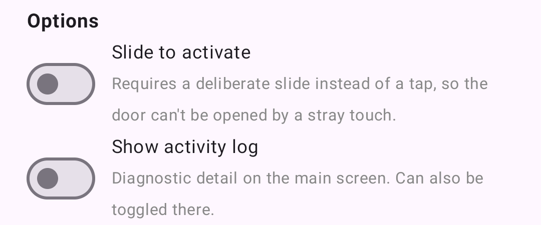
- The default control is a slider that must travel most of its length before it fires. A short nudge snaps back. The slider prevents unintentional presses. Choose between a Slider and a Plain Button in “Settings”.
- Addresses and credentials are not compiled into the app. “Settings” holds them. Local and internet HTTPS share the same web username and password. Bluetooth uses a separate shared secret. Leave a method's fields empty and that method does not appear. The same APK can be handed to someone else; they paste their own settings. Rotating a password or hostname does not require a rebuild.
- The app pins the device certificate's public key and will talk only to that key. That is why the self-signed certificate does not produce a warning inside the app.
Full source, including the HTTPS fork and the Android app, is on GitHub.
This writeup is free to use, modify, and share.
If it saved you time, solved a problem, or helped you avoid buying a new garage door opener, consider making a voluntary payment of any amount to support more work like this.
Questions, comments, complaints, and improvements are welcome.